
Mhira3D: the casting reveals the process
From casting integrity to process stability: how Mhira3D brings 3D vision and thermography together on the freshly extracted casting.
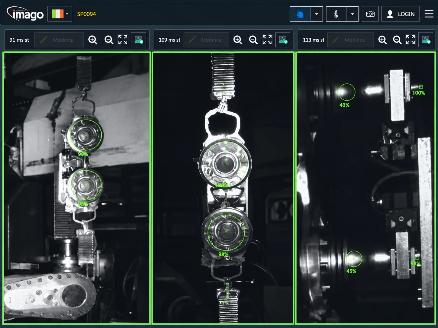
Reading the casting as it leaves the die
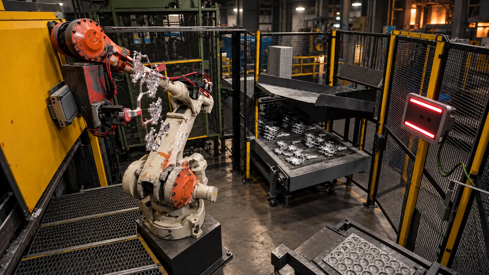
As the robot extracts a casting from the press, the part already carries important information about its quality and the condition of the die. A missing feature, an incomplete vent or an abnormal thermal distribution can reveal a problem before the casting reaches trimming and subsequent operations.
Imago developed Mhira3D around this point in the production cycle. The system inspects the casting while it remains in the robot gripper, combining three-dimensional analysis of its geometry with a reading of its thermal map. These complementary views of the same part make it possible to check integrity and follow process behaviour.
From part geometry to process monitoring
The project grew from Imago’s work alongside foundries and a practical requirement: checking casting completeness directly inside the die-casting cell. Three-dimensional analysis allows casting features to be inspected through configurable points and regions, adapting the inspection to different parts and the dies fitted to the press.
The introduction of thermography broadens that view. Alongside shape, Mhira3D begins to read the temperature distribution across the freshly produced casting. The part also becomes a source of information about the die: its thermal signature can reveal anomalies associated with cooling, lubrication and broken pins.
Development continues with dedicated algorithms and learned thermal equilibrium, allowing production cycles to be compared with a reference condition. In parallel, Giga-Mhira3D extends inspection to large castings. The project develops in two directions: gathering more information from the part and adapting the application to different production requirements.
Inspection after extraction
Inspection takes place after extraction from the press. The robot presents the casting to the vision head in the positions specified by the recipe; Mhira3D acquires geometric and thermal data, runs the configured checks and returns the results. The operator can identify the areas that triggered an alert and review the images associated with the part.
For the specified configurations, analysis takes less than 500 milliseconds. Integration into the cycle is assessed alongside robot positions and movements: validation within the cell establishes the overall timing and casting coverage.
Integrity in three dimensions
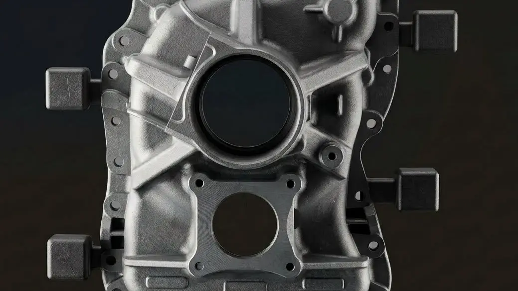
A missing injection overflow, an incomplete chill-vent or a missing casting from a multi-cavity die are among the conditions that 3D analysis can check. The recipe identifies the expected features and inspection regions, with acceptance criteria defined for the casting geometry.
Inspection can also cover casting deformation and the part’s position in the gripper before placement in the trimming press. Different severity levels for vents help distinguish situations that call for different responses. The result gives the operator an indication tied to the specific area and feature inspected.
Temperature reveals process behaviour
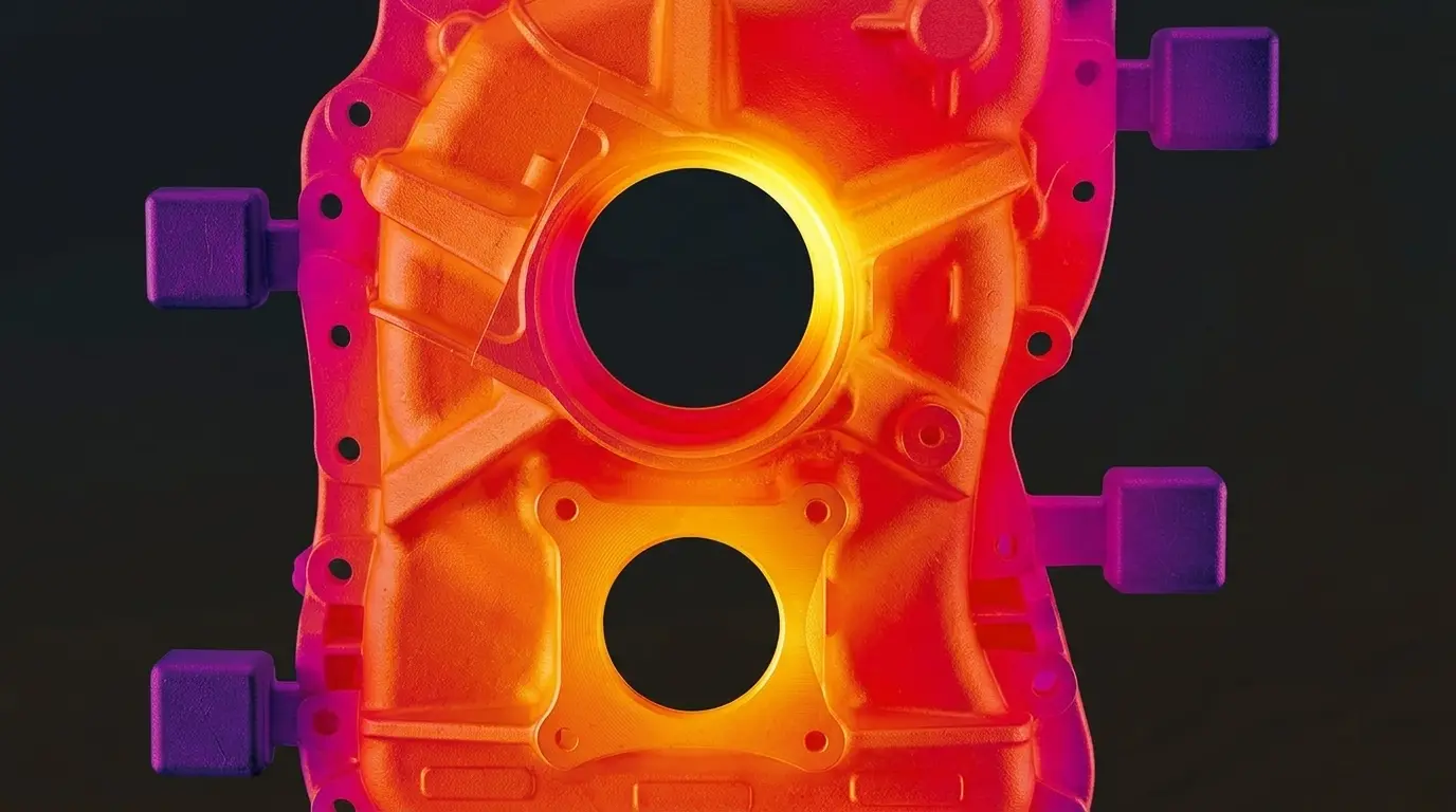
The casting’s thermal map carries the signature of the process that produced it. Observing how temperature is distributed across different regions, and how it changes between cycles, reveals behaviour that geometric inspection alone does not describe.
Mhira3D follows the critical areas defined in the recipe and flags variations associated with temperature-control or lubrication problems. Local overheating, abnormal cooling and gradual drift become information available to the operator. Analysis concerns the effects visible on the casting, which can indicate abnormal die conditions.
Learning the thermal equilibrium adds a reference for comparison between castings. During start-up and after a restart, the system helps operators follow the approach to expected conditions; during production, it highlights departures from the learned stability.
The challenge of broken die pins
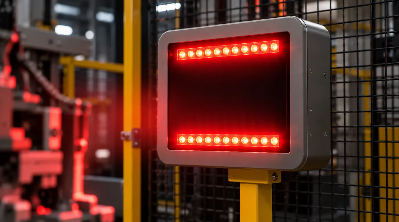
A broken die pin can compromise the casting and require attention to the tooling. To address this problem, Imago developed an algorithm that uses thermographic information to recognise the effects of the break on the part.
The alert is generated where Mhira3D observes the casting, immediately after the press. The operator therefore has useful information before the part moves through subsequent stages. This check illustrates the contribution of thermography: reading an anomaly on the casting that also concerns the condition of the die.
Development for large castings
The adoption of Giga presses introduces larger castings and new coverage requirements. Imago developed Giga-Mhira3D to bring the same inspection approach to these applications, through a configuration dedicated to high-resolution acquisition of large components.
For the intended applications, the casting can be acquired in a single image. Field of view, useful resolution and robot positions are defined for the component, with geometric and thermal checks after extraction remaining central. At this scale too, integration starts with the part’s features and the space available in the cell.
Designed around the cell
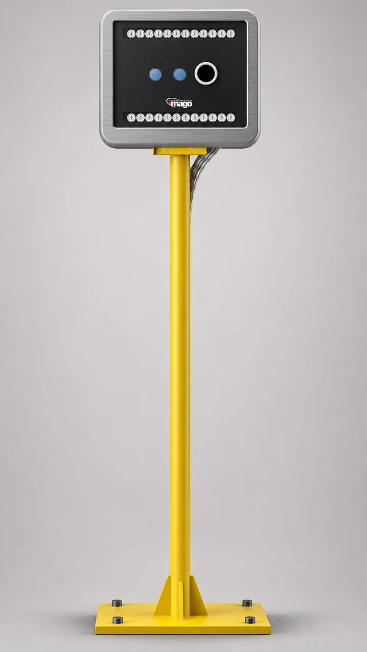
Mhira3D is configured around the cell where it will operate. The head combines 3D vision and thermography; the support, cabinet containing the processing unit and connections complete the system. Positioning and mounting take account of available space, robot movements and vibration.
Applications include aluminium and zinc castings, including Zamak, and single- or multi-cavity dies. Each installation is configured for the material and geometry to be inspected. Robot and PLC connections also follow the cell’s design, using digital I/O, Ethernet/IP or Profinet according to the planned integration.
From die changes to production data
At a die change, recalling the recipe restores the stored robot positions, inspection areas and evaluation criteria. For the specified configurations, this takes around two seconds. Creating and initially configuring a new recipe are separate activities, taking up to five minutes under the specified conditions.
The value of inspection continues beyond the result for an individual part. Images and outcomes are linked to inspection identification data and remain available through the interface. Exports and an optional connection to factory systems allow them to be used in production analysis.
Day-to-day operation takes place on the plant’s local network. An Internet connection can enable services such as remote support, while inspection remains operational within the factory network.
From casting to finished component
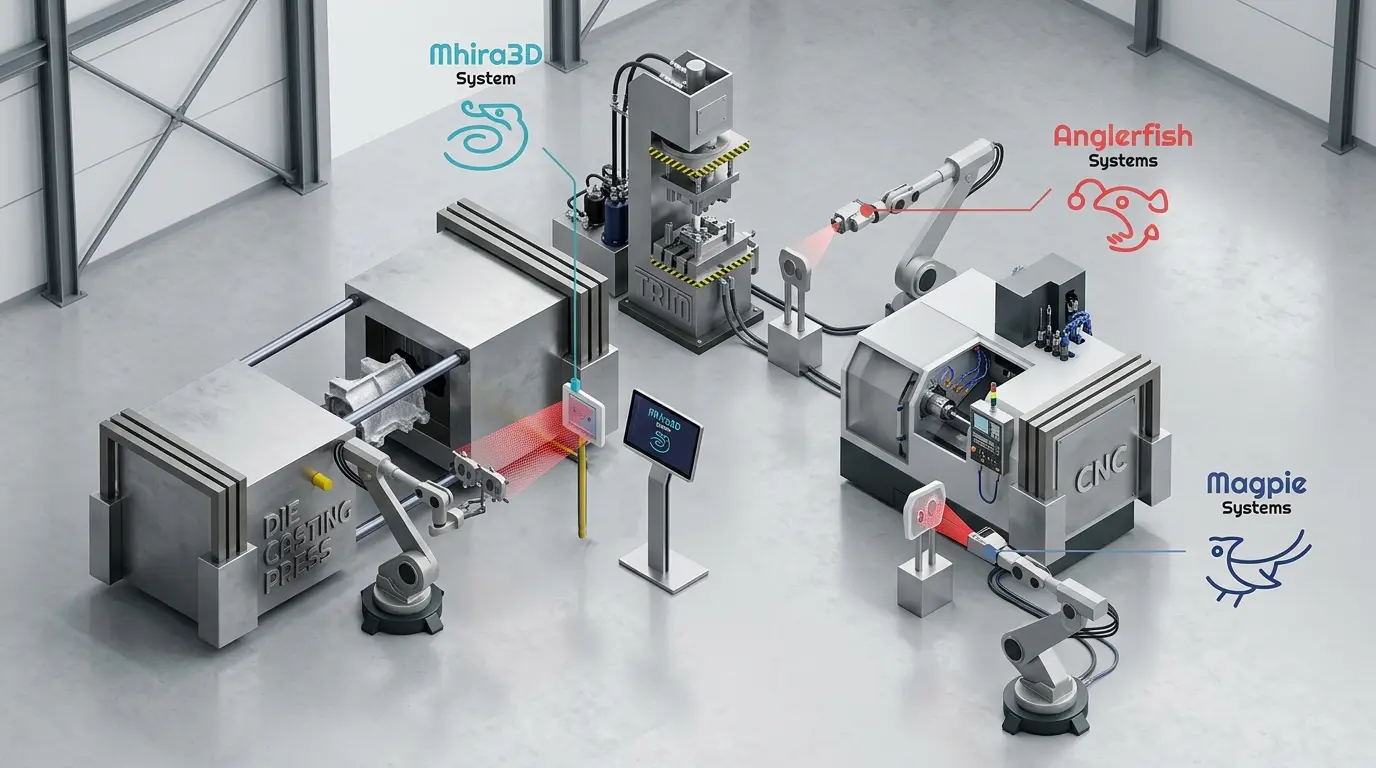
The casting inspected by Mhira3D moves on to subsequent production stages. After trimming, Anglerfish checks the trimmed part; after machining, Magpie inspects machined surfaces, including exposed porosity and burrs. Each system observes the relevant features at the point in the process where they become accessible.
Within this sequence, Mhira3D provides the first information about casting integrity and thermal behaviour. The project’s evolution has turned that inspection into a tool for understanding production: operators can locate an anomaly, compare it with earlier cycles and retrieve the part’s images. Geometry describes what has been produced; temperature helps explain how the die is operating.
Die casting and automotive
More case studies
All cases-
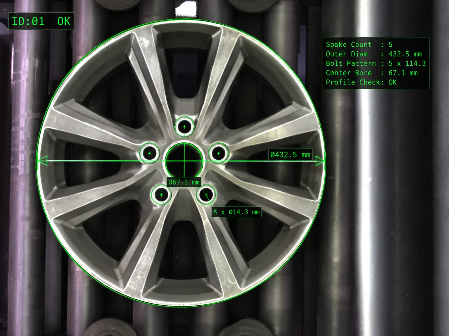
Illustration Die casting and automotive
Wheels: model recognition and orientation
-
Die casting and automotive
Ensat inserts and machined surfaces: height inspection
-
Die casting and automotive
Machined holes: presence, diameter and surrounding defects