
Mhira3D
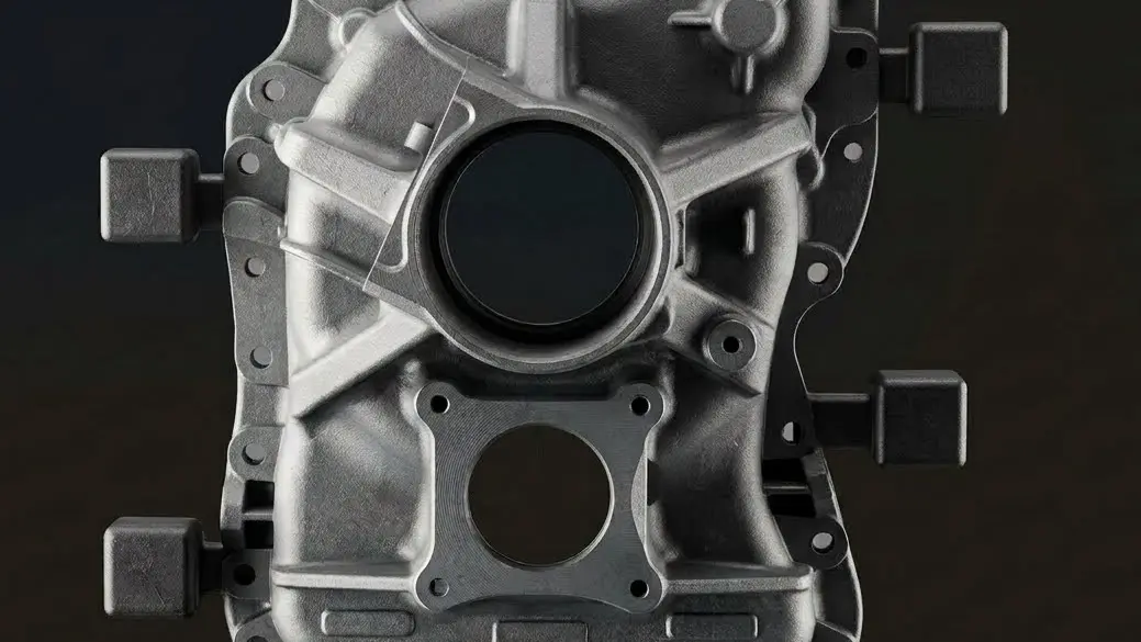
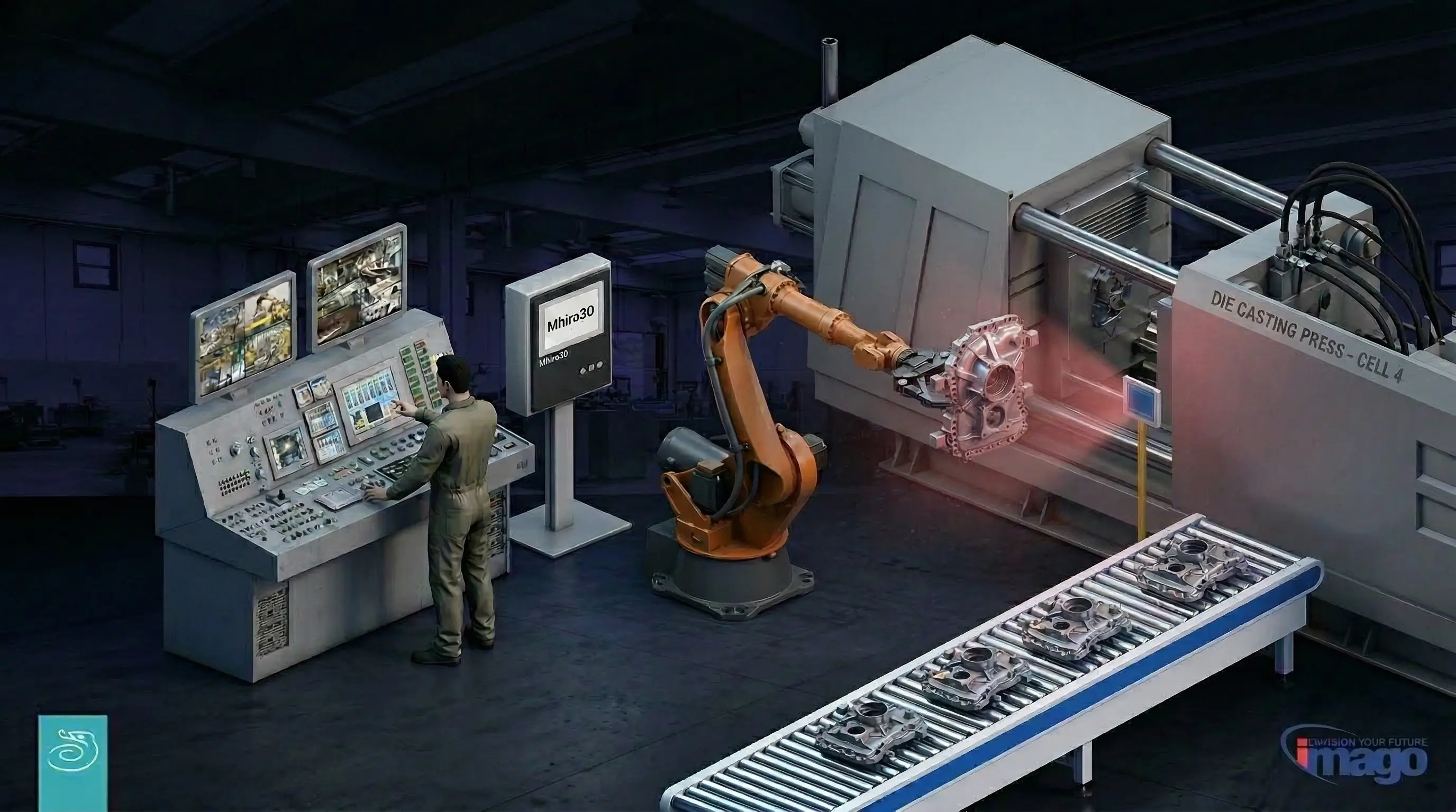
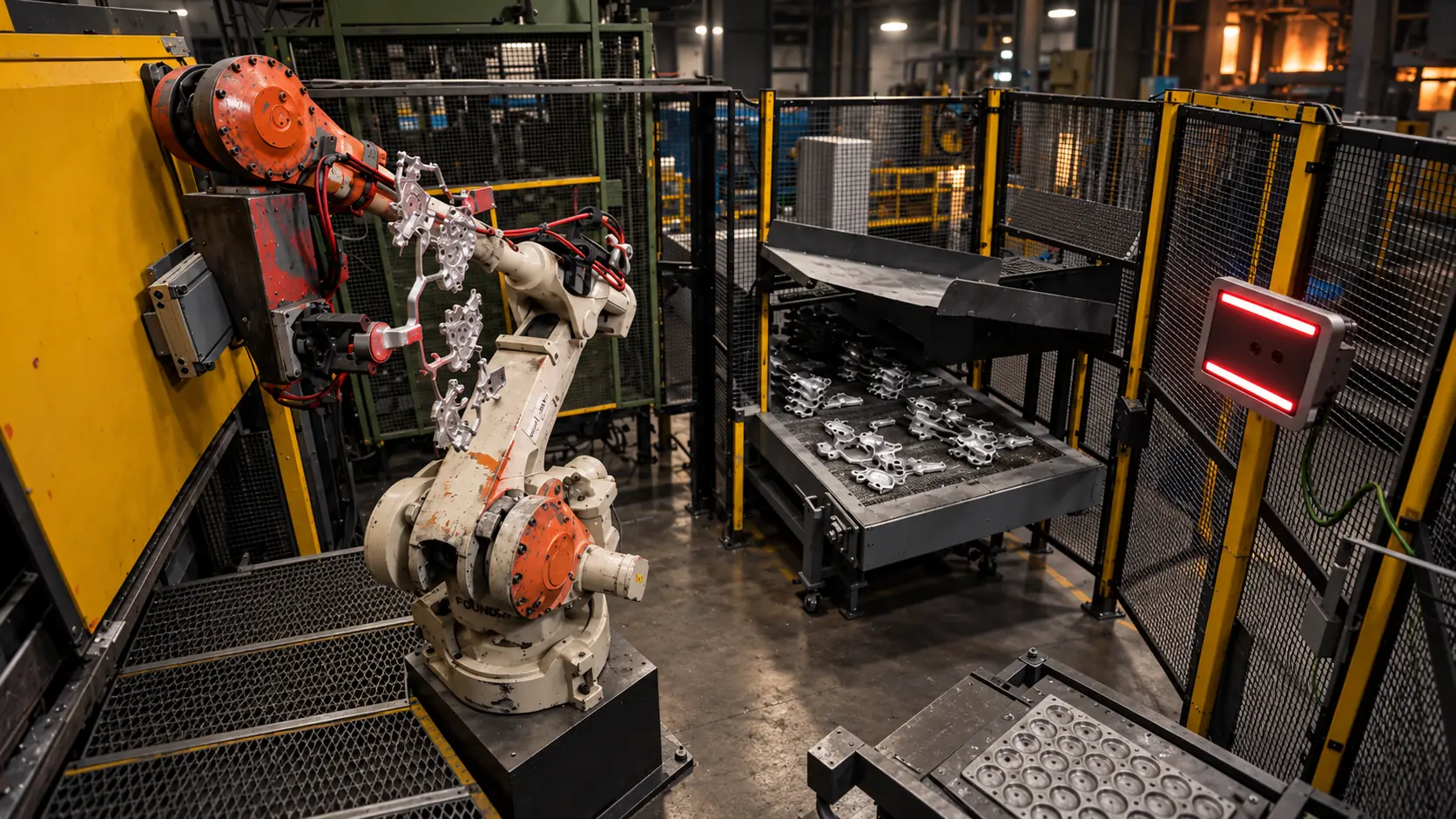
Mhira3D inspects the die-cast part in the robot gripper — three-dimensional integrity and process thermal monitoring — automatically and instantly.
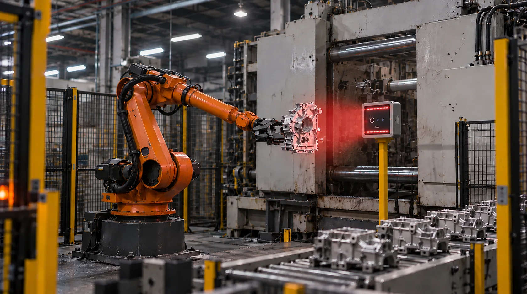
Geometry and temperature on the same casting
A single vision head captures the die-cast part’s 3D geometry and thermal map. Inspection takes place inside the cell, after extraction from the press.
The recipe defines robot poses, inspection areas and acceptance criteria. 3D analysis checks casting integrity, vents and injection witnesses; thermography detects broken cores and thermoregulation or lubrication anomalies.
Images and results are stored for each part. Comparison with the learned thermal balance supports the operator during startup, restart and production.
Extraction
3D analysis
Thermal analysis
Processing
Result and traceability
A field of view defined for the part
Single castings or multi-cavity dies, in aluminium or zinc: field of view, material, robot poses and integration are defined for the application.
One part. Two views
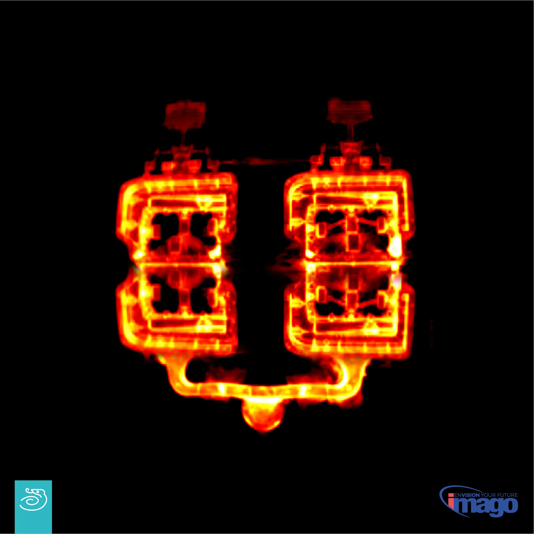
Geometry and thermal map, captured at the same instant.
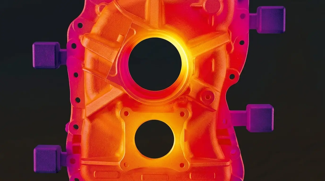
- T surface187 °C
- ΔT hot spot+ 8 °C
- Thermal variation– 12 °C/h
- CoresOK ✓
- Vents4 / 4 OK
- Gate witnesses4 / 4 OK
- Overflows100% ✓
Casting integrity and thermal process anomalies
Casting integrity
3D analysis checks completeness and integrity in the areas defined for the casting. The image highlights the regions that caused rejection.
Broken core detection
The thermal map signals the effects of broken die cores during the cycle. A patent application has been filed for this technology.
Incomplete vents
The system measures vent (chill-vent) completeness. Inspection points support multiple rejection levels, configured for different operating stages.
Process stability and restart
Mhira3D learns the process’s thermal balance and signals deviations. The comparison supports the operator during startup and restart and indicates a return to the learned stability.
Injection track anomalies
3D analysis checks injection witnesses in the poses defined by the recipe. Their integrity provides an indication of process conditions.
Thermoregulation and lubrication issues
Thermography detects anomalies associated, for example, with blocked thermoregulation channels or lubrication nozzles. Detection criteria depend on the effects visible on the casting and the inspection configuration.
Built for the foundry
Robust hardware
Industrial hardware designed to withstand the heat, fumes and harsh conditions of the foundry environment. System positioning is planned together with Imago's technicians to minimise routine maintenance. The software interface is designed for production floor use.
Fast recipe changeover
Each recipe defines robot poses and inspection points. For the configurations indicated by Imago, initial creation and configuration take up to 5 minutes; recalling a stored recipe takes about 2 seconds, from the interface or an external signal.
Inspection within the die-casting cycle
From casting inspection to recipe management: how Mhira3D fits into the cell’s operations.
| Aspect | Without Mhira3D | With Mhira3D |
|---|---|---|
| Defect detectionGeometric integrity of the die-cast part | Sensors in fixed positions, often on one side of the part |
Inspection areas and part sides defined in the recipe configuration. |
| Die core inspectionBroken or missing extraction cores | Difficult to automate |
Automatic in-line inspection, with timing validated for the cell. Inspection areas are defined around available poses. |
| Thermoregulation monitoringStatus of the die cooling circuit | Assessed from its effects on the part, afterwards |
Thermal reading at every cycle |
| TraceabilityData archiving for every part produced | To be organised with other systems |
Automatic: 3D images, thermal images and analysis data combined with the injection and part ID. |
| Startup and restartProcess stability after die change or stoppage | Relies on operator experience |
Automatic comparison with learned stability |
| Die lubrication anomaliesIssues with the lubrication and cooling system | Detected from downstream effects |
Anomalies detected thermally, in cycle |
| Format changeover timeTime to switch from one die to another | Often requires entering the cell |
Recipe recall in about 2 s, also via external signal |
| Format configurationInitial recipe setup for a new die | To be prepared for each new die |
Up to 5 minutes |
Vision head, support and cabinet
The head combines 3D vision and thermography. The support structure, electrical cabinet and connections are defined for the cell.
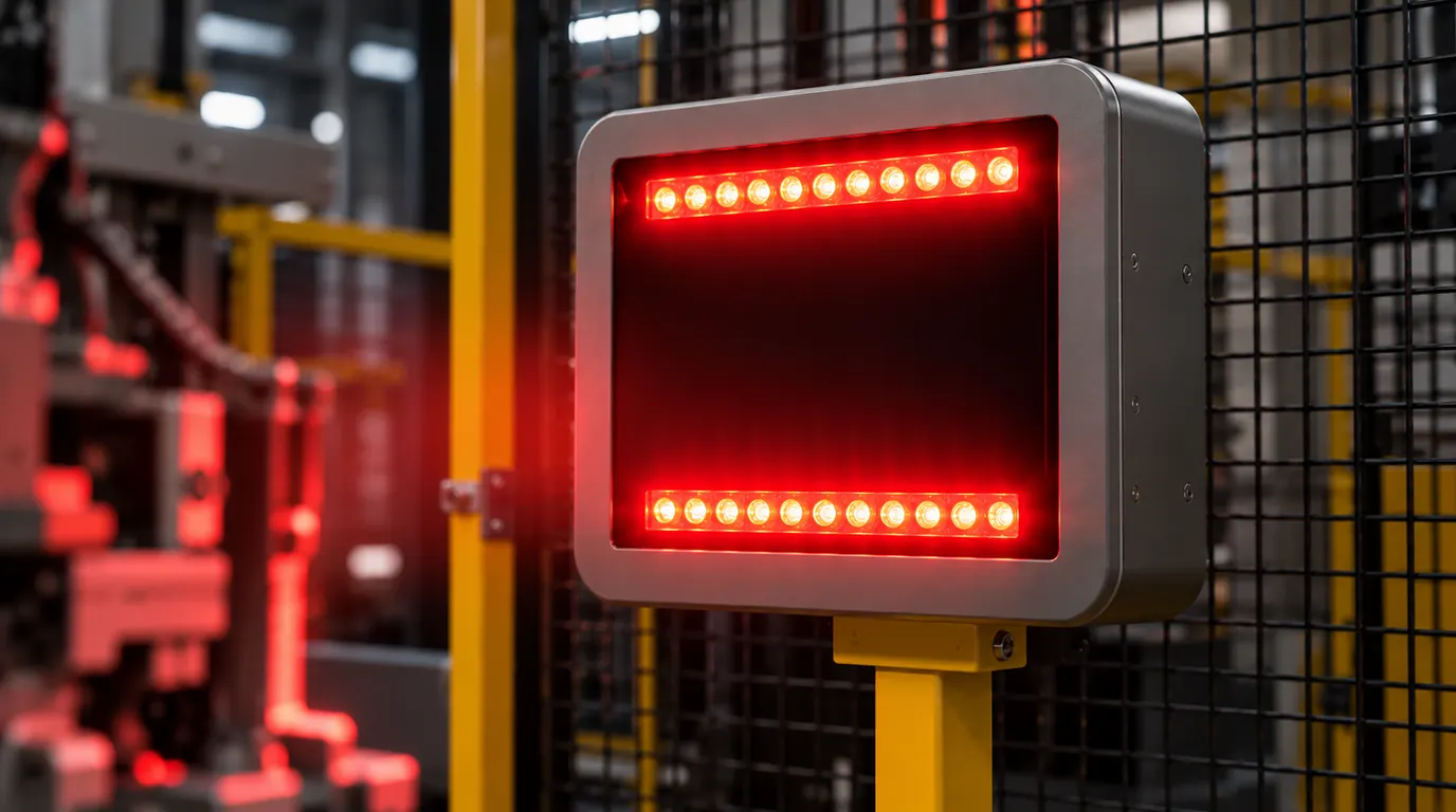
Vision head
3D cameras and thermal camera integrated in a single compact block, designed to withstand the temperatures, dust and vibrations typical of the foundry.
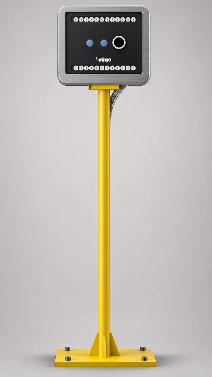
Support structure
Floor-mounted steel pole, positioned outside the robot's working area. Designed with Imago technicians for each specific cell.
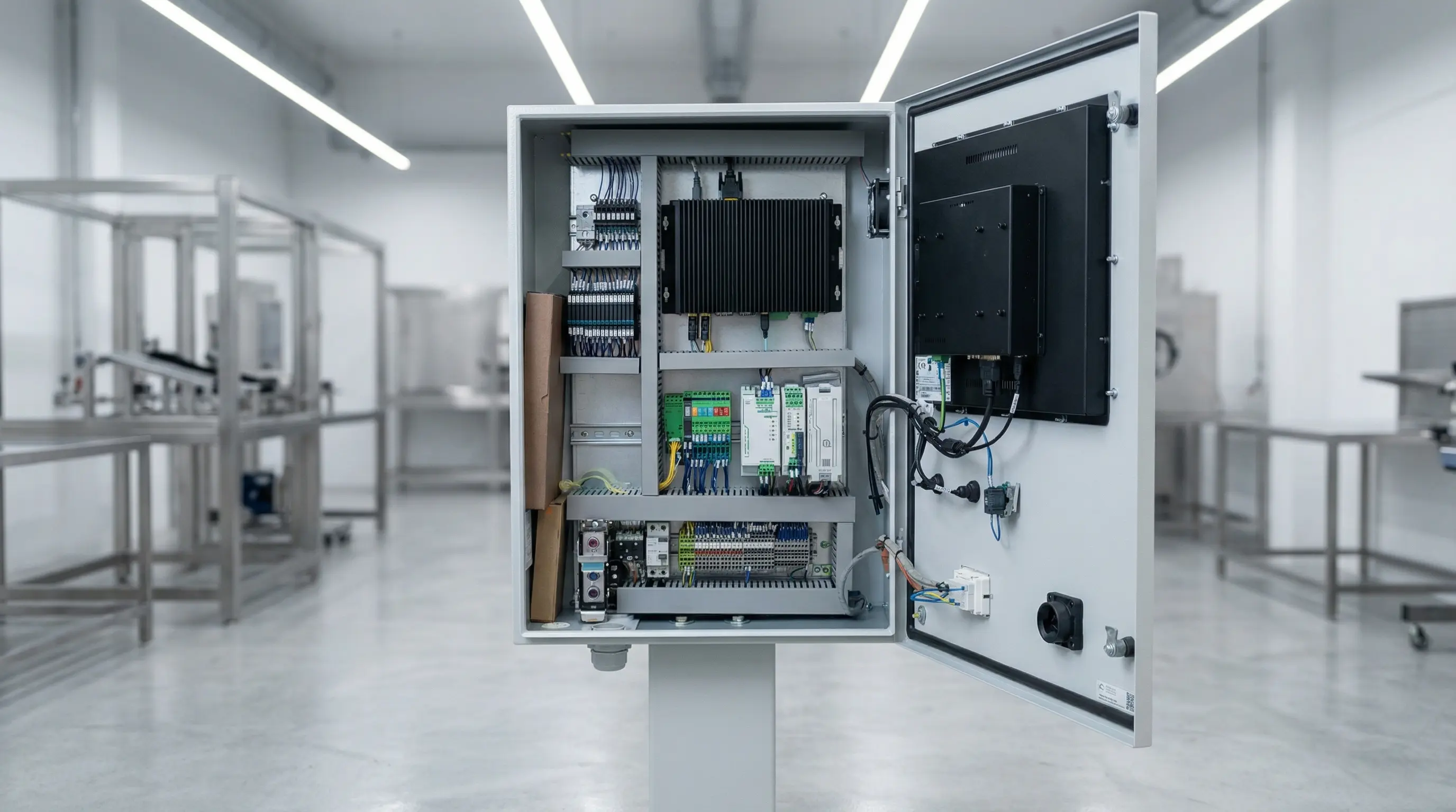
Electrical cabinet
Industrial PC, power supply and connections in a dedicated enclosure. Software interface accessible via touch monitor or remotely over local network.
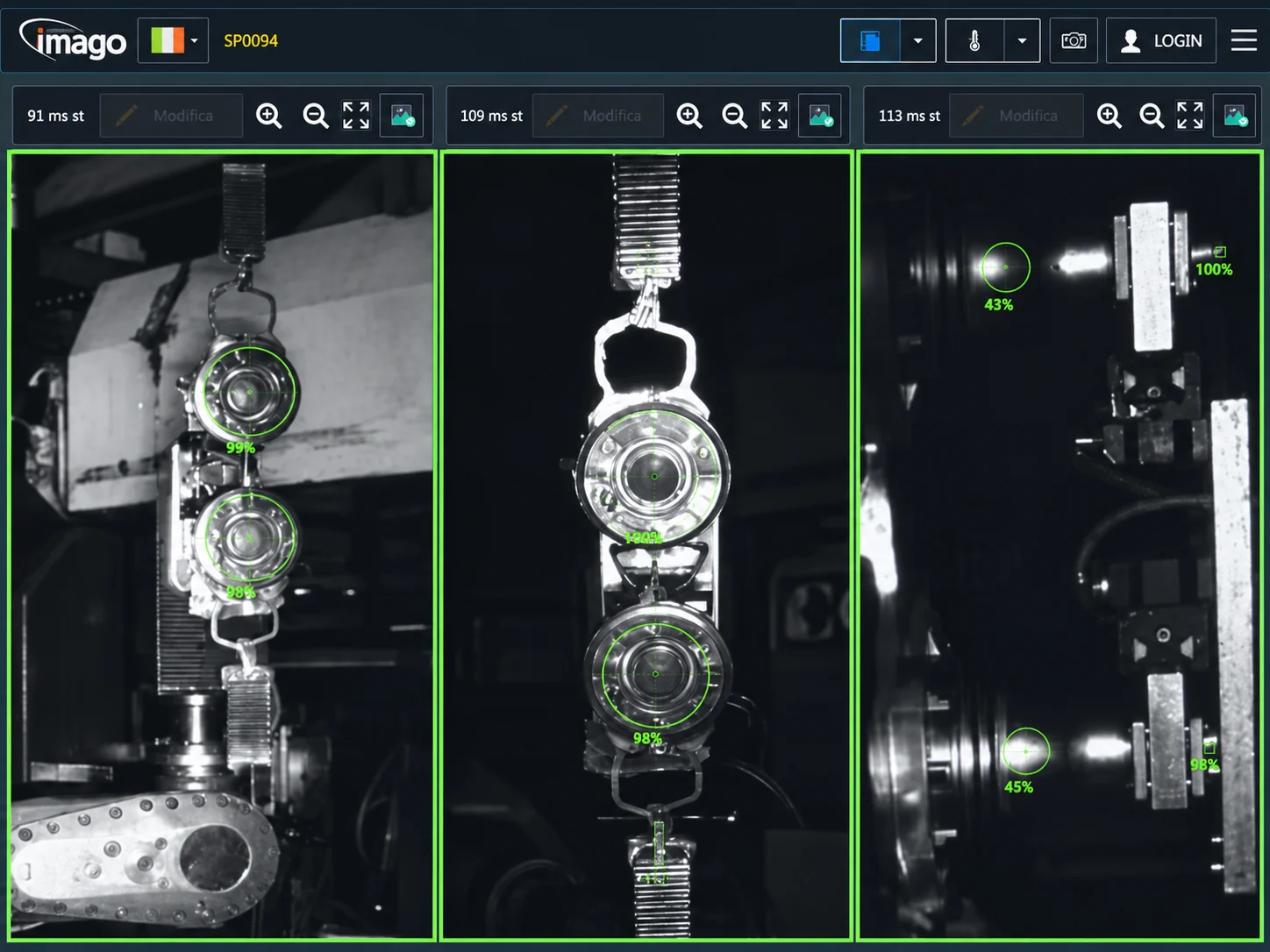
Software interface
Each view shows the acquired image with its inspection points, the score of each one and the analysis time. Accessible via touch monitor or remotely over the local network.
Mhira3D in the foundry
Films and images of the system in use.
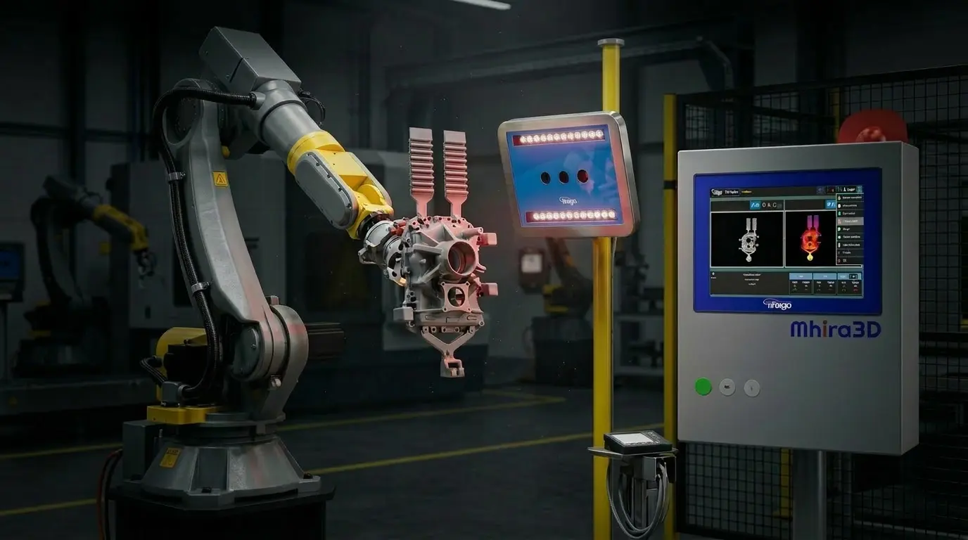
Mhira3D in foundries
From tier 1 automotive manufacturers to European die casting leaders.

























Frequently asked questions
Does it work with Zamak die casting as well as aluminium?
Mhira3D is used on aluminium and zinc (Zamak) castings. Material, geometry and thermal conditions are assessed for the required configuration.
Does it also work with large parts, Giga casting dies and multi-cavity dies?
Mhira3D can be configured for large castings and multi-cavity dies. Coverage, poses and cycle times are verified for the geometry and cell.
How does it integrate with robots and PLCs?
Robot and PLC integration is verified for the project. Integration options include Siemens and Allen Bradley PLCs and protocols such as digital I/O, Ethernet/IP and Profinet, subject to confirmation for the cell.
What is the installation and commissioning time?
Installation typically takes 1–2 days. Imago's technicians support the entire on-site commissioning process.
Are there any limitations for cell integration?
Mhira3D can be installed on new or existing cells without additional panels or covers; space, robot poses and mounting are checked for the cell. For stable images, the mounting structure must not be in contact with highly vibrating surfaces and is preferably fixed to the floor.
How long does it take to create, configure and recall a recipe?
Each recipe is configured independently in terms of number of poses and inspection points. Initial creation and configuration takes at most 5 minutes. Once created, the recipe is stored and recalled in about 2 seconds, from the interface or via an external signal.
What is it able to detect?
Mhira3D detects broken cores in the die, integrity and incompleteness issues, thermoregulation anomalies and lubrication system problems. It also supports startup and restart phases by monitoring process stability.
I'm concerned about having cameras in the cell. How often does maintenance need to be done?
The system is designed to be robust to foundry working conditions. Positioning is planned together with Imago's technicians to minimise routine maintenance. We recommend checking the vision head's optical surfaces monthly and, if needed, cleaning them with a cloth and alcohol.
If I need support, what should I do? What support services do you provide?
Imago supports customers after installation as well. A training course is included during installation and can be repeated later. Our technical support team is available during Italian working hours, plus dedicated support packages to meet various needs. We operate with two partner companies worldwide — one in the United States and one in the Czech Republic.
How is each part's data stored and made available?
Every measurement is automatically stored with a timestamp, part ID, 3D and thermal images, and the result for each inspection point. Data can be viewed in dedicated screens directly in the software interface, or exported in standard formats (PDF, CSV). It is also accessible externally for MES integration, and a Power BI service is available for remote data consultation.
Is an internet connection required for operation?
No. Mhira3D operates in fully offline mode, within the plant's local network. An internet connection is not required for daily operations.
Die casting and automotive
Which casting needs inspection?
Assess 3D and thermal inspection in your die-casting cell. Every installation is tailored to the specific needs of your production.
Discuss your production cell